Utilizing CFD Analysis to Optimize Vessel Ventilation
When envisioning the future of vessel design, considerations for heating, ventilation, and air conditioning (HVAC) may not always take precedence. Yet, the significance of proper HVAC systems cannot be overstated, particularly when it comes to ensuring optimal passenger experience. Among the critical aspects of HVAC, ventilation and air circulation onboard vessels stand out as pivotal factors in maintaining healthy and clean air environments.
In this paper, we delve into the key role that Computational Fluid Dynamics (CFD) analysis plays in optimizing vessel ventilation systems. By leveraging advanced simulation techniques, vessel designers and engineers can not only enhance passenger comfort but also prioritize their health and well-being. From mitigating airborne contaminants to regulating temperature and humidity levels, the application of CFD offers multifaceted solutions to the complex challenges inherent in HVAC design for maritime environments.
Computational fluid dynamics (CFD) is an analysis technique that uses numerical mathematics and data structures to analyze and solve problems of fluid flow. In a CFD simulation, volume is discretized, or divided up, into many millions of smaller individual volumes. The fluid flow through each of the smaller volumes can then be calculated to determine the flow characteristics throughout the entire volume. Using this technology, ventilation systems and interior compartments can be digitally modeled to observe the airflow and compare the depth and path of discharge. More sophisticated CFD models can also be used to analyze the flow and dispersion of particles throughout a space or to consider the impacts of convection in compartments with large temperature gradients. The digital model allows for rapid testing of many different ventilation configurations.
Vent styles, locations, sizes, and flow rates can all be adjusted until an optimal ventilation arrangement is found.
In ship design, the most prevalent use of CFD is to predict hull resistance and determine propulsive power requirements of a hull model. Due to the relative accessibility of hull numerical model creation and modification, CFD has allowed naval architects to optimize hull shapes through use of many iterations, zeroing in the hull shape that provides the least propulsive power required to meet a design speed. Often, but not always, the CFD analysis results are validated using a traditional physical hull model run in a towing tank. Building the physical model, and iterating its shape followed by a towing tank test for each hull shape modification is significantly more costly and time consuming than using the virtual model and numerical iterations of CFD. Other tests that have traditionally been performed in towing tank; wake measurement, seakeeping, maneuvering, shallow water testing and most other types of testing can all be simulated through CFD analysis. The traditional physical model testing in a towing tank still has its place, but for most projects, the cost effectiveness and expediency of a CFD analysis is the approach of choice for a new or modified hull design.
While propulsive power prediction is the most common application of CFD in ship design, the many possible applications of CFD to what happens above the waterline may be just as beneficial. These include superstructure wind resistance, fire propagation prediction, toxic and flammable gas dispersion, and ventilation systems optimization. This article will focus on smart ventilation design and systems optimization through the use of CFD tools.
Smart Ventilation System Design
Before any development of a heating, ventilation and air conditioning (HVAC) design, let alone optimization of the vessel design, the objectives must be clear. The broad design objectives of any HVAC system are:
- Be sufficiently sized to meet the heating and cooling requirements of the vessel. This starts with knowing the ambient environment in the regions that the vessel will operate. These are often expressed as interior temperature and humidity requirements when outside air temperatures are at their near worse case in both the heating season and the cooling season. One design objective might be to provide cabin heating sufficient to maintain 72 degrees F when outside air temperature is 20 degrees F in the region of operation. Similar is true for sizing the air conditioning system.
- Distribute the air in a balanced fashion so that all locations within a conditioned space get sufficient air flow and there are no locations over ventilated or under ventilated.
- Be quiet, appropriate to the space it serves. Ventilation noise is annoying at least. Pilothouse and accommodation spaces need to be much quieter than machinery spaces. Often the design criteria is expressed as maximum DBa limits for each space served. To put this into a practical perspective, ventilation noise should be able to be ignored and forgotten by an occupant in the space.
- Be effective and efficient. A poorly designed HVAC system will neither meet its design objectives or be energy efficient in doing so.
- Assure good indoor air quality.
- Meet regulatory requirements for air exchange rates and fire isolation.
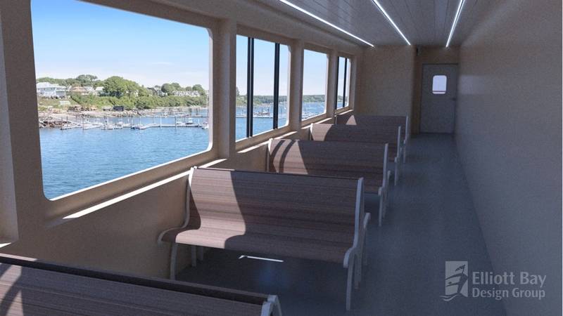 Optimized ventilation design can enhance the overall passenger experience while onboard. Image courtesy EBDG
Careful attention to each of these objectives during design will result in a ship's ventilation system that is comfortable for the occupants, provides a healthy indoor environment and is energy efficient. Many of the objectives described above can be facilitated and predicted in the design phase through the use of CFD before they become construction problems to be resolved at much greater cost. Similarly, existing vessel problems with ventilation can often be identified and a design solution developed before costly and sometimes ineffective modifications are made.
Providing healthy and comfortable indoor air begins with assuring that the outdoor air brought into the ventilation system is as clean as possible. Conventionally designers have used intuition and experience to locate the fresh air intakes. Good design practice includes separating fresh air intakes from air discharges as widely as possible to prevent short circuiting and locating fresh air intakes away from engine and boiler exhausts, sewage and fuel tank vents to prevent particulates, noxious and toxic fumes from being pulled into the ventilation system. Conventional design practice alone does not always work to assure that the air entering the intakes will be clean.
Ships superstructures, being the irregular shapes that they are and moving in all headings relative to wind direction, make locating intake air openings challenging. The challenges become greater with smaller vessels with smaller superstructures, "wide separation" of exhausts and intakes becomes a relative term. A CFD analysis can facilitate the ideal placement of air intake openings when in proximity to exhaust discharges and tank vents. It can even predict under what conditions clean air intake becomes bad air. Sometimes the solution isn't relocating the air intake but slowing down the air velocity across the intake louver, adding a fashion plate to increase separation distance, or reshaping an exhaust discharge to create a greater projection of the exhaust gases away from the vessel. These issues get addressed through the design process to optimize the system.
HVAC system optimization is important for shipboard energy efficiency as well as reducing system weight and costs, but also for passenger comfort and safety. Harmful pathogens such as norovirus, respiratory syncytial virus (RSV), Covid-19, pneumonia, tuberculosis, influenza (the flu), and even the common cold continue to be able to spread through the air, ship operators have had to consider what can be done to mitigate shipboard airborne pathogen transmission.
While the struggles of virus containment are well documented on cruise ships and other crowded spaces, the pervasiveness of airborne pathogens has demonstrated that it is just as important for smaller vessels to take steps to reduce the spread of infections as well. Proper mitigation techniques may help prevent crew members from spreading infection to one another or reduce the risk of passenger vessels becoming the site of a so-called "super spreader" event.
In this article, we will be examining one of the opportunities for pathogen containment that should receive consideration from ship operators: the ventilation system. Traditionally, ventilation system design has concentrated on the number of air changes per hour (ACH) in a particular space. While increasing the ACH is known to improve the dilution factor of infectious agents, thereby reducing the possible spread of disease through infectious particles, it does not increase the ventilation system's effectiveness. In other words, not all air changes are equal. We must think beyond a simple exchange rate to the actual dynamics of air movement within a space.
Two opposing factors must be considered when optimizing a ventilation system to reduce the risk of airborne particle transmission: depth of exchange and path of exchange. Here, depth of exchange refers to how much of the space has received fresh air (outside or filtered) after one exchange cycle and path of exchange refers to the distance the air must travel before exiting a space.
Designing a ventilation system for minimal airborne particle transmission requires a balance of both factors, maximizing the depth of exchange while minimizing the path of exchange. This is best explained by comparing the images in Case 1 and Case 2. These figures represent a simplified two-dimensional space with a ventilation inlet in the lower right corner and a ventilation outlet in the upper left corner. The arrows represent two different hypothetical paths of airflow through the space, with green representing fresh air and red representing air already present in the space.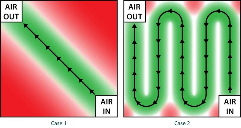 Image courtesy EBDG
Case 1 has a poor depth of exchange because, even though the total volume of air exchanged may meet a certain ACH rating, the airflow is such that the corners of the space receive little to no fresh air after an exchange cycle. Conversely, the airflow in Case 2 results in an excellent depth of exchange as nearly all parts of the space are filled with fresh air after one exchange cycle. Having a high depth of exchange is important for removing airborne contaminants from wherever they originate in a space. Imagine if a sick passenger were seated in the upper right corner of the space. In Case 1, removing the infectious particles from the air would take much longer as there is little to no airflow in that corner. But in Case 2, removal of any infectious particles is ensured due to the high depth of exchange.
Let us now consider the path of exchange. Case 1 represents a good path of exchange, meaning the distance the air must travel before exiting the space is as short as possible. Case 2 has a poor path of exchange because the air must travel a very long distance before exiting the space. To understand why this is important, imagine now that a sick passenger is seated in the lower right corner near the air inlet. In Case 1, infectious airborne particles are efficiently removed from the space, minimizing the potential to pass by other passengers and infect them. In Case 2, infectious particles are carried by the airflow through the entire space, increasing the likelihood that they could infect passengers in other areas along the path to the outlet.
While it may be easy to imagine an improved ventilation arrangement for the idealized space presented above, visualizing the airflow to balance the depth and path of exchange is much more difficult in actual practice. The airflow is not only affected by the complex three-dimensional space of shipboard compartments, but furnishings, equipment and people within the space can alter the path of the air as well. Fortunately, modern day engineering analysis tools such as CFD are up to the task and can be used for fluid flow visualization and overall system optimization.
The CFD analysis begins with creating a three dimensional (3D) digital model of the hull and superstructure. It needs to be accurate in its dimensions and shape but can generally be devoid of most details unless they are large items that can disturb airflow. Fluid (air, water, gas, etc.) flow modeled over the hull and superstructure will simulate the vessel underway at various speeds as will modeling the net flow influence from various directions to simulate wind conditions. Engine and boiler exhaust discharge can be added to show exhaust gas projection and dissipation, as shown in Figure 1.
Fresh air intake flows can also be added.
Visual representations of analysis results will show the pressure gradients over the superstructure as well as flow direction vectors and velocities. It is well known that fluid flows from areas of high pressure to low pressure, but finding and tracking the pressure gradients is made much easier through the CFD visualization tools. It is even possible to particle trace, e.g. a pathogen, and watch its defined entry point through its path along the vessel until it has left the system. Figure 2 shows particle tracing of exhaust gases emanating from exhaust stacks. Inside air would be shown in a similar way.
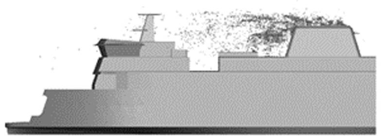 Figure 2: Exhaust particle tracing
Areas of concern revealed through flow visualizations can be corrected and rechecked until optimized for all conditions of vessel operation. Once the CFD model is set up, iterating solutions is simple and cost effective. Conventionally this type of analysis was done in a wind tunnel at great cost using a smoke wand and yarn taped to a physical model. Iterating solutions was prohibitively expensive; CFD iterations of model changes and re-analyzing can be a matter of hours versus wind tunnel iterations taking days or weeks to make changes and re-analyze. With CFD, the entire domain (the vessel and its environment) is digitized and point information is available anywhere in the domain.
While focusing on one aspect of the ventilation system often reveals a second area that needs attention. That second area has already been analyzed by the computer and the data can be immediately accessed. With a wind tunnel, if a secondary area wasn't anticipated in the initial testing, more test setup, rerunning the tunnel test would be necessary.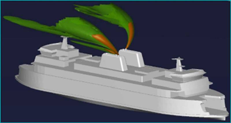 Figure 1: Exhaust gas concentration with a two-knot head wind
Once built, vessels need to serve their mission for decades. HVAC systems take up an inordinate amount of space and must be designed as an integral component of the vessel structure, superstructure shape and interior space arrangements. They also use a significant portion of the power available. Sub-optimal design is inconvenient and annoying at least and, more significantly, may affect the health and safety of all persons onboard. Correcting sub-optimal ventilation design once installed is often challenging, invasive and expensive or may even be cost prohibitive or otherwise infeasible. CFD analysis of ventilation systems is a cost-effective tool that can be applied in initial design or in modification to assist the designer and operator in achieving and assuring all of the objectives of optimal HVAC system installation are met.
About the Authors Mr. Drew Matz is a Naval Architect for Elliott Bay Design Group specializing in vessel stability, computational fluid dynamics (CFD), structural and piping design, as well as vessel electrification design concepts and feasibility. Drew's expertise spans steel ship functional design, 3D modeling, and calculation development for various vessels, from ferries and barges to luxury yachts. In addition to his naval architecture expertise, Drew brings a proven record of managing complex projects with coordination of multiple stakeholders ensuring projects are completed on time and on budget.
 Mr. Brian King joined EBDG in 1988 and in his last full-time position was President - Chief Engineer until retirement in May 2021. Brian now serves as Principal Emeritus supporting client relations and supporting strategic objectives, providing expertise in planning, business management, engineering, and sales. Throughout his tenure, Brian significantly contributed to EBDG by establishing engineering standards, leading recruitment and training initiatives, managing technical resources, and implementing quality assurance programs.


