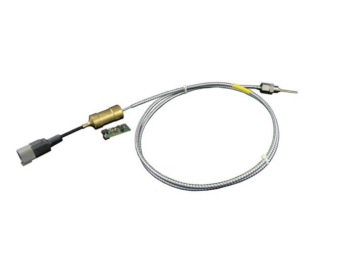
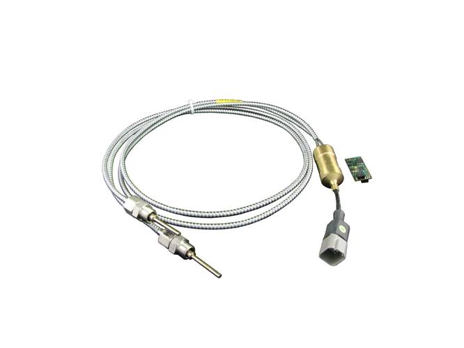
CMR Group’s chief technical officer, Patrice Flot, considers the current approach to sensing exhaust gas temperature (EGT) on high horsepower engine platforms and the capabilities provided by new digital technology.
An EGT sensor measures the temperature of the engine exhaust gas to prevent damage to critical components such as the after treatment system, turbines and cylinder head exhaust valves. It can also be used inside the combustion chambers where hot gases are generated.
Exhaust gas temperature does not provide an accurate measurement but gives a good indication of heat in the cylinder during combustion, and is most commonly measured close to the head. Since all metals melt, deform, or undergo transformation under excessive temperatures, too high a temperature can cause damage to engine components and therefore it is critical to have a sensor in place to assess the combustion inside the engine, either across the whole unit or cylinder by cylinder.
Operating at peak levels, EGT can optimize engine performance and deliver significant fuel and maintenance cost savings. Any abnormal change in the combustion cycle due to the fuel supply system, air supply system or combustion chamber configuration can obviously be problematic so having sensors currently located on an engine is vitally important.
Exhaust gas is a mix of fuel components characterized by temperature, pressure and mass flow; which are all constantly changing in the exhaust pipe during every combustion cycle. At the exhaust outlet of the cylinder head, gas temperature can range from around 800°C during exhaust valve opening to 40°C during exhaust and inlet valves opening overlap. Considering a medium/high speed engine running at 1200 rpm, this can see extreme changes in temperature up to 10 times per second. During each cycle, the temperature sensor located at the cylinder head will be exposed to the heat and cold exhaust flow.
The intermediate temperature observed depends on the location of the sensor on the exhaust pipe outlet, the length of the sensor plunger (in comparison with the diameter of the exhaust pipe), the materials of the sensor – and the corresponding thermal coefficients – and the design of the sensor itself.
And typically, when electronic sensors were introduced, many engines retained double measurements: thermo-mechanical to provide a local reading and an electronic one to produce a remote output – providing two different yet acceptable reading references. The EGT measurement at the cylinder head outlet is not an absolute value, providing an indicative value that is highly repetitive from day-to-day when engine load, speed and conditions are the same.
The most common use for this information has been and continues to be, EGT monitoring devices, which survey individual and average values, as well as temperature gradients: they deliver pre-alarm and alarm status by comparing each individual value to the average value. By monitoring individual gradients, the devices can also detect if any cylinder showing an abnormally fast or slow EGT value change.
For a turbine gas outlet, the pulse effect is dampened by the blades and therefore temperature variations are within -/+ 1°C. The measurement provided is used to accurately evaluate the amount of energy produced in the exhaust while also being used to calculate the gas temperature at turbine inlet. This not only provides an indication about the thermodynamic behavior of the engine but the real status when compared to the theoretical values of mathematical modeling.
EGT sensors, sited on the hot areas of the engines, pose some significant challenges for cable, which might have to withstand surrounding temperatures that can reach as high as 600°C depending on where they are located. Here, Mineral Insulated Cable (MIC) is used for the hot spots before being connected to flexible cable running across cooler parts of the engine.
The electronics cable must also be resistant to problems caused by water or humidity ingress, and carefully routed to minimize damage caused by gas leakage at the flanges of the exhaust pipes - leakages might be slight, not even detectable through engine performance but nevertheless, they can hit the cable when close to the flanges. How much the cable can meet the requirements of any excessive or abnormal engine servicing, typically when heat insulation is incorrectly refitted around the pipes following maintenance, is also an issue to be considered.
Digital Future
The tendency to add more and more sensors to engines has added a new challenge to the complete wiring system, affecting both reliability and component costs. For instance, larger connectors on ECUs can be vulnerable during routine maintenance programs: a single contact damaged inside the connector can be costly, resulting in the whole unit being rendered unfit for purpose.
This together with improvements in materials, design, technical applications and CAN protocol has driven increasing numbers of engine manufacturers to look at the capabilities offered by a new generation of digital technology, which heralds significant competitive advantages over the very first sensors.
Today, it is possible to equip engines with an array of sensors fully digitized to comply with the CAN bus protocol. (The protocol usually refers to the data link layer protocol defined by ISO 11898-1 and the physical layer defined by ISO 11898-2 and can be summarized as: The physical layer uses differential transmission on a twisted pair wire. A non-destructive bit-wise arbitration is used to control access to the bus.) The speed and position sensors, and ON/OFF switches can also be digitized, thus reducing the wiring system to a single cable CAN loop on the engine.
Purely digital engines lie in the future but the first steps are now being taken by far-sighted manufacturers, who are starting to adopt digital sensors to sit alongside traditional ones on their engines. In part, this is being driven by the restrictive number of analogue input ports available on ECUs. Now, digital technologies are offering an advantage: any additional number and combination of CAN exhaust-after-treatment, turbine inlet/outlets, cylinder head outlet, combustion chamber temperature and liner wall temperature sensors can be connected to the existing ECU.
These sensors can incorporate unique series numbers embedded in their software and delivered with temporary addresses, or with pre-set ones. And when plugged into the CAN loop, they can easily be recognized as different sensors because of their series number, despite ‘carrying’ the same address. Software tools enable the engine builder to create the address in the factory via a PC and a simple CAN interface, address that is uniquely allocated to given and unique function on the engine.
The superior ‘intelligence’ digital sensors offer is set to herald a whole new world of possibility when it comes to new functionalities. For example, it will be possible to have the various sensors communicating with each other, sharing their respective values. This will enable them to calculate an average value and deliver pre-alarm and alarm when an individual value starts to stray too far from the mean.
The EGT sensors can also record the number of low frequency cycles (start/stop of the engine; start/stop of voltage supply to sensor) and the high frequency combustion cycle. It can then perform residual lifetime estimation and provide the expected ‘date for change’ information, which delivers improved condition-based maintenance and longer term cost savings. Eventually, considering that similar intelligence will be embedded in every sensor, this approach will see the possibility of splitting the software of the ECU into sub-programs that, if one sensor fails, will re-route to another one, delivering improved reliability and all round system performance.
The ‘Internet of Things’ Sensor
There’s no question that EGT sensors are becoming a ‘must have’ technology to assess the health of the valve actuators for fuel injection, whether liquid or gas, and the health of the after-treatment systems on industrial engines. Any issues surrounding digital complexities can be overcome as most engine end-users are industrial organizations, who have requisite experience in dealing with automated systems and digital device management. Indeed, we are seeing confident users, who know that sensor manufacturers such as CMR Group will provide them with easy-to-use maintenance and management tools.
Engine builders are also recognizing the benefits of digital technology that facilitates rapid implementation of additional sensors, without any physical change in input/output ports of the ECU. This is allowing almost unlimited additional reserves of sensors compared to original design capabilities - the complexity of harness design is reduced as any additional sensors only require an additional harness connector, without an increase in size or additional wiring.
Finally, digitization is pushing back the spares’ business from third parties to OEMs who are managing the whole engine control software. This is providing greater safety for the end-user thanks to the availability of original parts, while reducing instances of engine damage caused by incorrectly sourced instrumentation and component parts.
Current technologies have minimum and easy-to-use functionalities but no doubt the future will offer much more: the capability to release the ECU from its high load and support CBM systems while offering an ‘Internet of Things’ sensor that can deliver clever data to remote parts of the world, regardless of time zones.
The Author
Patrice Flot is chief technical officer at CMR Group. He will present a paper on “New sensor technology for EGT” at the 4th Int. Conference SENSORS for Exhaust Gas Aftertreatment and CO2-Reduction, June 27-29, 2017 in Augsburg.


